Interesting.
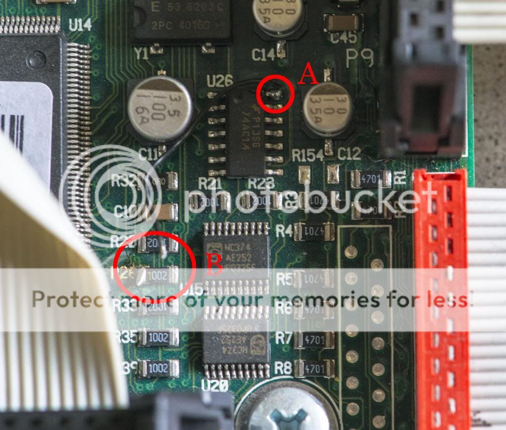
The chip the wire is attached to is a Schmitt trigger with six channels; it pretty much just cleans up a noisy electrical input signal - think MIDI, buttons, etc. However, the pin the wire is attached to is the power supply (Vcc), which is at +5 volts in this case. Likely the only reason this chip is involved is that someone wanted a source of +5 volts. It is possible that the PCB trace to the Vcc pin on that chip is damaged (or otherwise less than ideal), but then I would think the wire wouldn't be going to R26.
The big chip on the left is likely the Freescale (Motorola) ColdFire micro controller (MCU) that controls all the hardware (like the DSPs) in the G2, scans the keyboard and buttons, handles MIDI, etc. R26 is an SMD resistor and the marking 1002 means it is a 10k Ω resistor (first three digits x 10^last digit so 100 x 10^2 = 10,000). This is likely a pull up (or down) resistor for a floating in- or output on the MCU (ColdFire).
If R26 is connected to an input (on the left side), one goal may have been to prevent that input from ever seeing a low signal by connecting +5v directly to it. If R26 is indeed a pull up resistor (and the contact on the right is also always at +5 volts), they could also have replaced R26 with some solder (to create a bridge). If R26 is connected to a pin that is used as an output, I see two options; if the right contact on R26 is at +5 volts, then the pin R26 is connected to a current sink that tries to pull the signal low or if the right contact on R26 is at 0 volt, it is likely a current source.
To summarize this bla bla, I can say I think that the chip is an 'innocent bystander' and that R26 is either connected to an in- or output. The question is: what?
I think it is best to cover the bare end (b) with some tape for now, so it cannot touch anything else in there and put +5 volts on it which might even cause a short circuit (hopefully the fuse would pop before that happens though). This may be some kind of factory mod that came loose, but I don't expect it to be because I would've expected it to be done in a more proper way that doesn't put any mechanical stress on the solder joints (i.e. by affixing the wire to the PCB or some sturdy component with some glue).
If it turns out it is indeed some custom mod someone did, I would personally just snip off the wire near point A and not even desolder it.
I think you should take care of that bare wire end, but since it otherwise seems to be working fine, don't mess with it any further.
