Page 2 of 3
Re: Midi Thru Sockets
Posted: 26 Mar 2014, 01:21
by ricard
True. Like with the other Swedish manufacturer of synthesisers (Elektron), producing their machines locally rathar than outsource manufacturing to China means they will be pricey, and they have to produce something with a unique look and feel to justify the price.
Re: Midi Thru Sockets
Posted: 30 Mar 2014, 19:13
by chvad
After this thread I decided to play with some more stuff regarding the midi out port on the Lead 4 and I need to bring to attention something else that makes this problematic. No MIDI through. Got it. There is a soft through option to use. Got it. Problem? Every passive through box I connected to the Lead 4 MIDI out doesn't work. A lot of these boxes require a small amount of power supplied over the MIDI cable to function. The Lead 4 does not supply this power. So if you are looking to a viable MIDI through option without having to plug in another device on stage, you can't look to the Lead to play well with this.
Re: Midi Thru Sockets
Posted: 30 Mar 2014, 21:18
by Professor
chvad wrote:The Lead 4 does not supply this power.
My NL4 does supply power over MIDI. Here's a picture of it powering a MIDI Solutions Thru box.
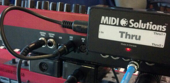
- uploadfromtaptalk1396207068181.jpg (36.78 KiB) Viewed 2897 times
Re: Midi Thru Sockets
Posted: 30 Mar 2014, 22:53
by chvad
wow. ok. i have that EXACT same through and that isn't whats happening at all. It's not the cable or through as Ive confirmed both working elsewhere. ugh... thanks for posting this!
Re: Midi Thru Sockets
Posted: 31 Mar 2014, 00:36
by pablomastodon
Nords are not designed to provide power to external devices and this is not recommended. Note that this power supply scheme is not midi spec (at least, it didn't used to be -- perhaps that has changed?), but an optional scheme which some instrument makers have enabled in their instruments.
Pablo
Re: Midi Thru Sockets
Posted: 31 Mar 2014, 02:19
by Professor
Great. Now if I need to make a warrantee claim, everyone has seen a picture of my Lead 4 with three external MIDI boxes stuck to it with Velcro. Here’s my workaround (if the Nord’s power over MIDI ever fails). The battery-powered MIDI Mouse is simple and handy.

- IMG_20140330_165946_895.jpg (33.61 KiB) Viewed 2866 times
Re: Midi Thru Sockets
Posted: 31 Mar 2014, 03:44
by Professor
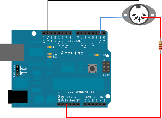
I found difficulty researching the shrouded MIDI specifications. But here’s some interesting evidence. On the Arduino website, there is a tutorial for connecting an Arduino (a popular hobby-level microcontroller platform) to an electronic instrument through MIDI.
In the tutorial, the data transmission signal is wired to pin 5 of the socket, the ground is on pin 2, and the author shows 5 volts wired through a 220 ohm resistor to pin 4. When I did the tutorial, I skipped the 5 volts because I was thinking that’s the power over MIDI which I don’t need to play notes. It worked great! [Note: this wiring scheme can introduce ground loops so a permanent device should use opto-isolators.]
FWIW, my Lead 3 has a solid 5.00 volts across pin 2 and 4 (both out and thru), the battery powered MIDI Mouse has 5.09 volts, my vintage Oberheim has 5.08 volts, my Lead 4 has only 3.32 volts, and last and least is the Electro 3 with 3.30 volts.
The confusing thing is, the Electro 3 has only 0.02 volts less than the Lead 4, but the Electro 3 is my only Nord that will not power a thru box.

I guess none of them should...
[Also note: a static voltmeter reading gives no indication of the available power of a voltage source to drive the intended load.]
http://arduino.cc/en/Tutorial/Midi?from=Tutorial.MIDI
- MIDI_bb.png (40.58 KiB) Viewed 2860 times
Re: Midi Thru Sockets
Posted: 31 Mar 2014, 11:51
by ricard
The MIDI 1.0 spec should be freely available in various locations on the 'net. I found a copy within half a minute of googling.
Anyway, it is surprising that you got it to work without connecitng pin 4. MIDI is implemented as a so-called current loop, which means that in order for the MIDI IN to receive data, there has to be a current path from pin 4 on the sending device, to pin 4 on the receiver, through the opto coupler on the MIDI input, back through pin 5 on the reciever, then via the cable to pin 5 on the sender. In order to switch the current on and off thus providing signaling, it is customary to have an open collector logic gate connect pin 5 to ground at the sender's end. That's why the TX pin on the Arduino picture above is connected to pin 5.
The ground at pin 2 is purely for grounding the cable shield. It is not intended to be used in the signal transmission. In fact, the MIDI spec says that pin 2 should be left unconnected at the receiving end.
If you have a non standard MIDI input which for instance measures the voltage level between pin 5 and the ground level at pin 2, then that would work without connecting the pin 4.
The MIDI standard does not specify a voltage on the output, only that the current loop should provide (at least) 5mA to drive the input. Thus, having 5V or 3.3V on the output should be irrelevant as far as the MIDI spec goes, but with 3.3V the resistors need to be proportionally lower to get the same current flowing.
So far the theory. MIDI processing boxes which have no separate power supply draw on the fact that usually one of the pins in the MIDI out is more or less directly connected to a positive voltage supply. Using the MIDI output in this way really violates the spec, but often enough works well enough and is extremely practical. When MIDI was conceived, the output voltage was always +5V because that's what the microcomputers at that time used. These days, it's becoming increasingly popular to have systems that only run on 3.3V, without a 5V line being present in the design. Logically, the MIDI outputs on such a device would also only run at 3.3V.
Now I don't know because I've only used very few of these MIDI powered devices myself, but I could well imagine that many manufacturers have designed them, especially older units, to run on 5V, not considering the fact that certain devices would only deliver 3.3V. It could well be that 3.3V is a borderline condition for some devices, so that some individual units would work and some not.
As Professor notes above, the voltmeter just reads the unloaded voltage, which does not tell the whole story. The amount of current available will be limited by any resistors in series. That would explain why certain devices will and other devices will not power a given MIDI through box, even though they apparently output the same voltage.
Re: Midi Thru Sockets
Posted: 31 Mar 2014, 18:34
by Professor
Awesome! This is much more clear to me now. I finally found a free copy of the MIDI spec. My previous search terms took me to the MIDI Manufacturers Association and they want 60 bucks to download the document.
If I understand this correctly, the voltage on pin 4 is supposed to be wired through a pull-up resistor. It's not intended to be for power over MIDI. A pull-up or pull-down voltage causes a data input to be forced to high or low (on or off, one or zero) when the data signal is inactive. That way, data signals are clearly on or off, and not floating somewhere in between.
I have tinkered with microcontrollers a little, and I occasionally forgot to use the pull-up or pull-down concept on the inputs. This will give intermittent results. Sometimes the input would read the voltage state correctly, sometimes not. That may explain why my Arduino tutorial experiment worked without the pull-up voltage.
Re: Midi Thru Sockets
Posted: 03 Apr 2014, 10:10
by ricard
When thinking of electrical signals, it's most intutive to think in terms of voltage. If there is a voltage, say 5V, the signal is active, if not, the signal is inactive. The term 'pull-up/pull-down resistor' is often used in this context, to get a defined voltage level if the transmitting device at some point provides an 'open circuit', i.e. no defined voltage. Technically, what is happening is that if the transmitter is not driving the signal line high or low, the impedence on the line is then infinite, which means it becomes sensitive electrical interference coming through the air - in essence, it becomes an antenna. The pull-up/pull-down resistor lowers the impedence to a level where the signal line is much less susceptible to interference. The resistor on the other hand must not be too small, or the transmitter will need to provide a lot of power to change the state of the line to the active state.
However, MIDI uses the current flowing through the optocoupler in the receiving unit as a means of signalling. There are a couple of advantages of this. Firstly, by using an optocoupler it's easy to provide so-called galvanic isolation between the transmitting and receiving device, which basically means that there is no common electrical connection, and in practice it means that it completely avoids earth loops through the MIDI interface. The second advantage is that since the impedence of a current sensing input is very low, it is not very susceptible to electrical interference.
To get to my point, the resistor tied to +5V is not a pull-up resistor, it is not there to get a defined voltage level. It's part of a current loop which runs from the +5V line, via the resistor to the MIDI out pin 4, to the MIDI in pin 4, through the optcoupler, back to the MIDI in port on pin 5, then to the MIDI out pin 5, and finally to ground via the TX output of the transmitter, which can be a so-called open collector output which means it has two states, one of which is a short circuit to ground, and the other is open. Thus either current is flowing or not, which constitutes the signalling protocol. Most other forms of digital communication utilize voltage levels, for instance serial ports which have negative voltage for active and a positive voltage for the inactive state.
In actual fact, the resistor tied to +5V needn't be there at all, since it's a current loop, the resistors can be located anywhere. Technicall, one could have one on the TX line connected to pin 5, and nothing on pin 4, i.e. having pin 4 directly connected to +5V. However, that would mean that a broken cable with a short circuit in it could short circuit +5V to ground, in effect short circuiting the power supply of the transmitting device. That's why it's customary to put resistors in series with both pin 4 and pin 5, in order to limit the current flowing in the event of a short circuit.
Thus, omitting the connection to +5V (either directly or via a resistor) will, if the receiver follows the MIDI standard, cause the current loop to be open at all times, thus no current will flow and no signal can be transferred. That's why it's surprising that omitting the reistor will work under any circumstances.
Then again, there may be devices which utilitize the fact that the output from a MIDI device is usually constructed the way it is (i.e. an open collector output), and using an internal pull-up resistor and a voltage sensor can receive the signal as a voltage. I once built a MIDI thru box that worked this way, simply because I didn't want the signal degradation that occurs in the opto coupler (whose transfer function is usually rather sluggish), and since it was a thru box, it would be coupled to other devices galvanically isolated inputs anyway, and besides, the run of cable from the sending device's MIDI output to the thru box input was to be rather short in my case, and thus not very susceptible to interference. I don't know if there are commercial devices which operate in this manner, but it would mean that the current that normally drives the optocoupler would be available to power the device instead.
Technically though, the signal output from a MIDI output could be on pin 4 instead of pin 5, with pin 5 grounded (either directly or via a resistor). Since the goal is causing a current flow/no-flow situation in the receiver it doesn't matter. But I've never seen an output constructed this way. There's no real advantage, and it doesn't really follow the example laid out in the MIDI standard either.